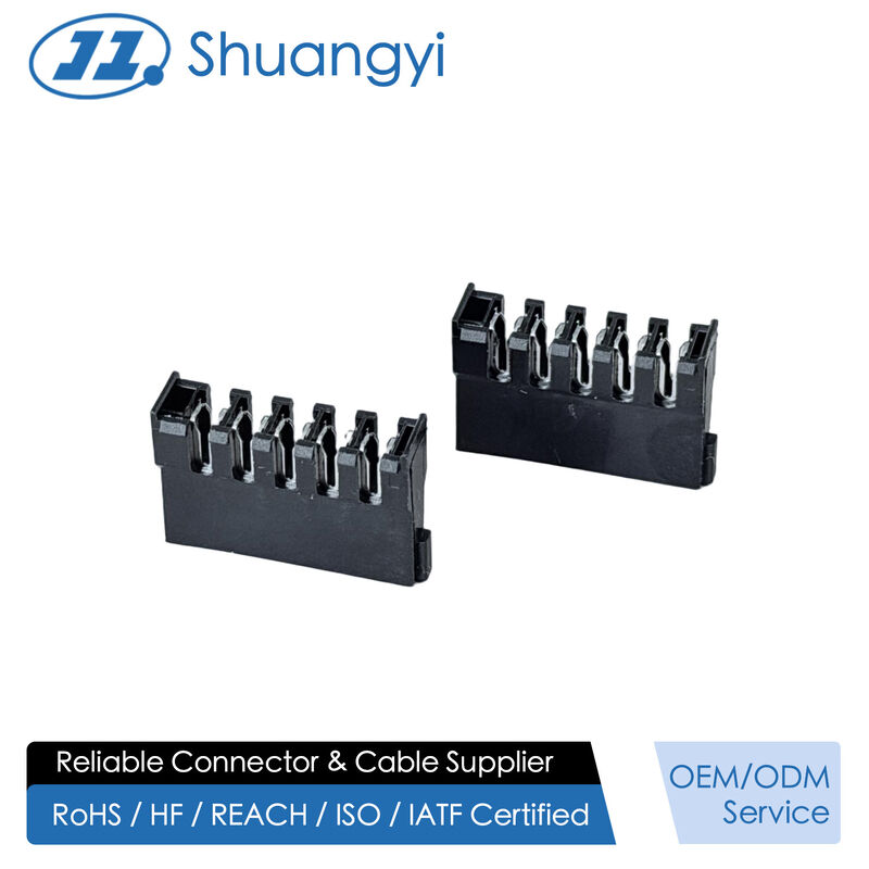
Our SATA connector series is designed for stable data transmission and high reliability. With customizable pin count, pitch, materials, and plating specifications, we offer tailored solutions for diverse applications. Produced in our automated facilities with strict quality control, these connectors ensure excellent durability, heat resistance, and hot-swap performance. Widely used in computers, servers, and industrial storage devices, they deliver precision connection and long-lasting performance.
ShuangYi Precision — Powering Smarter Connections.
Why Choose Us:
• Free samples available for quality evaluation.
• Support for both OEM & ODM customization.
• Trade Terms: EXW, FOB, CIF, CPT, etc.
Notice: The displayed price is only for reference. Contact us now for the best offer and detailed quotation!
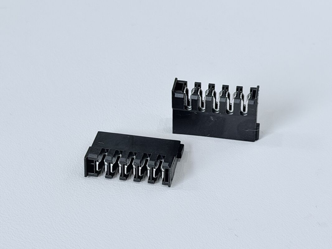
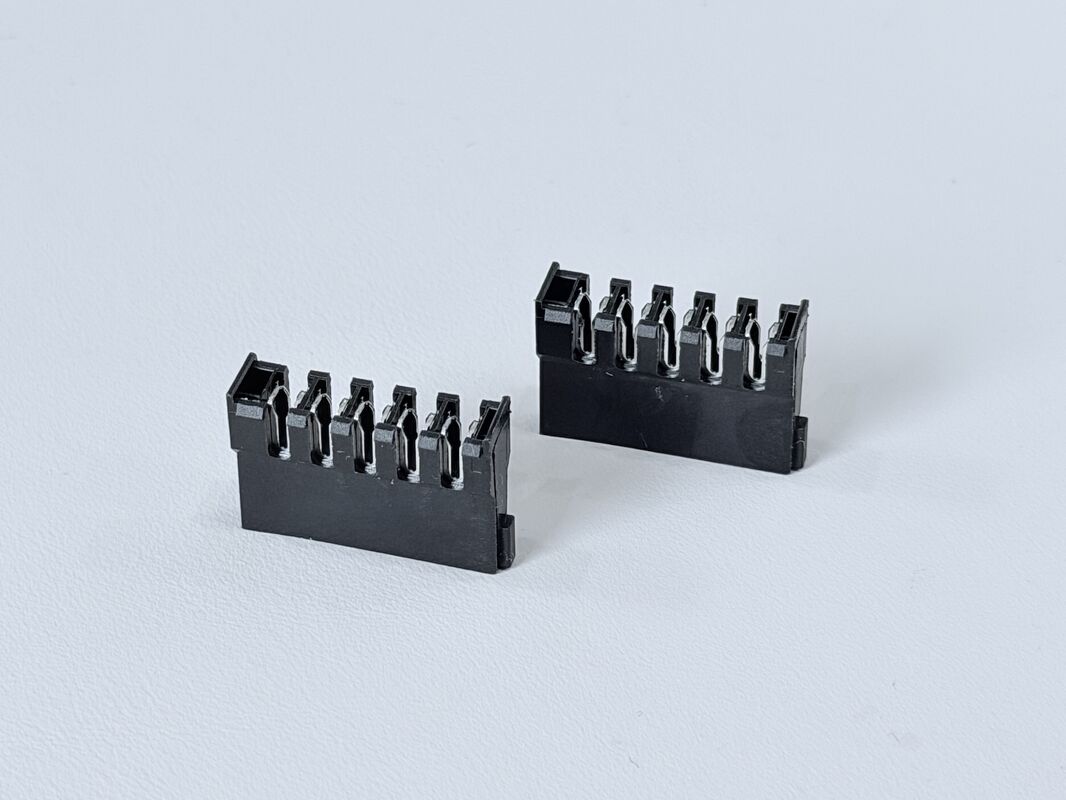
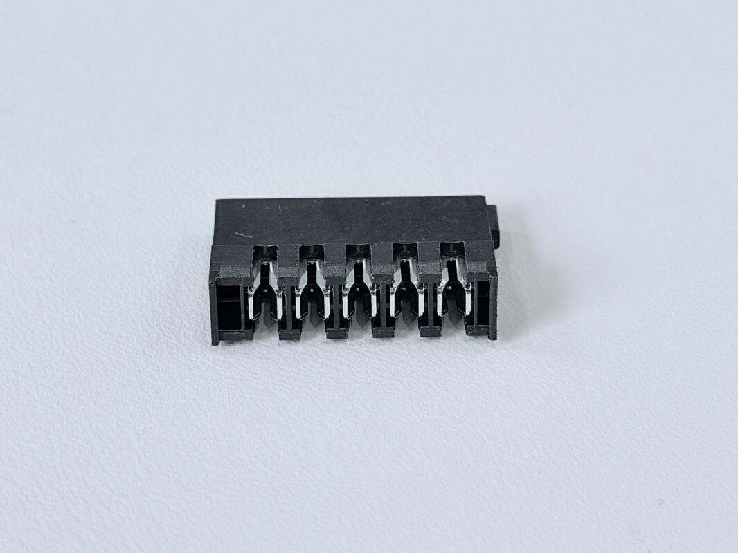
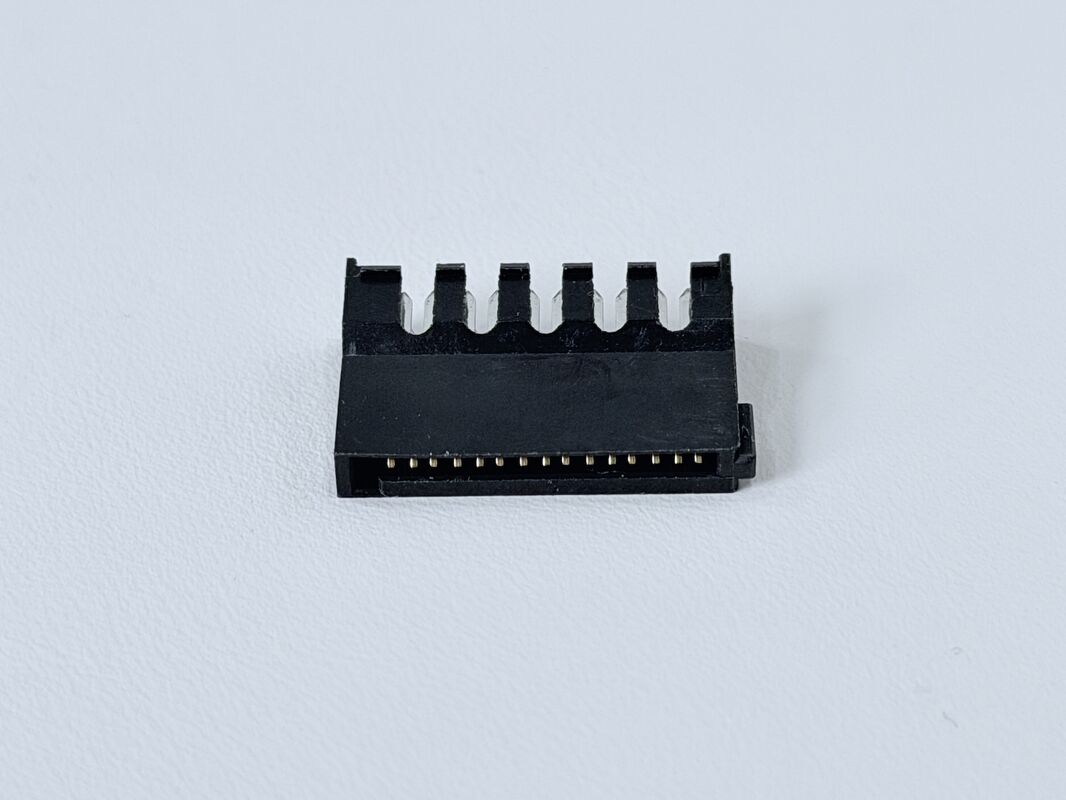
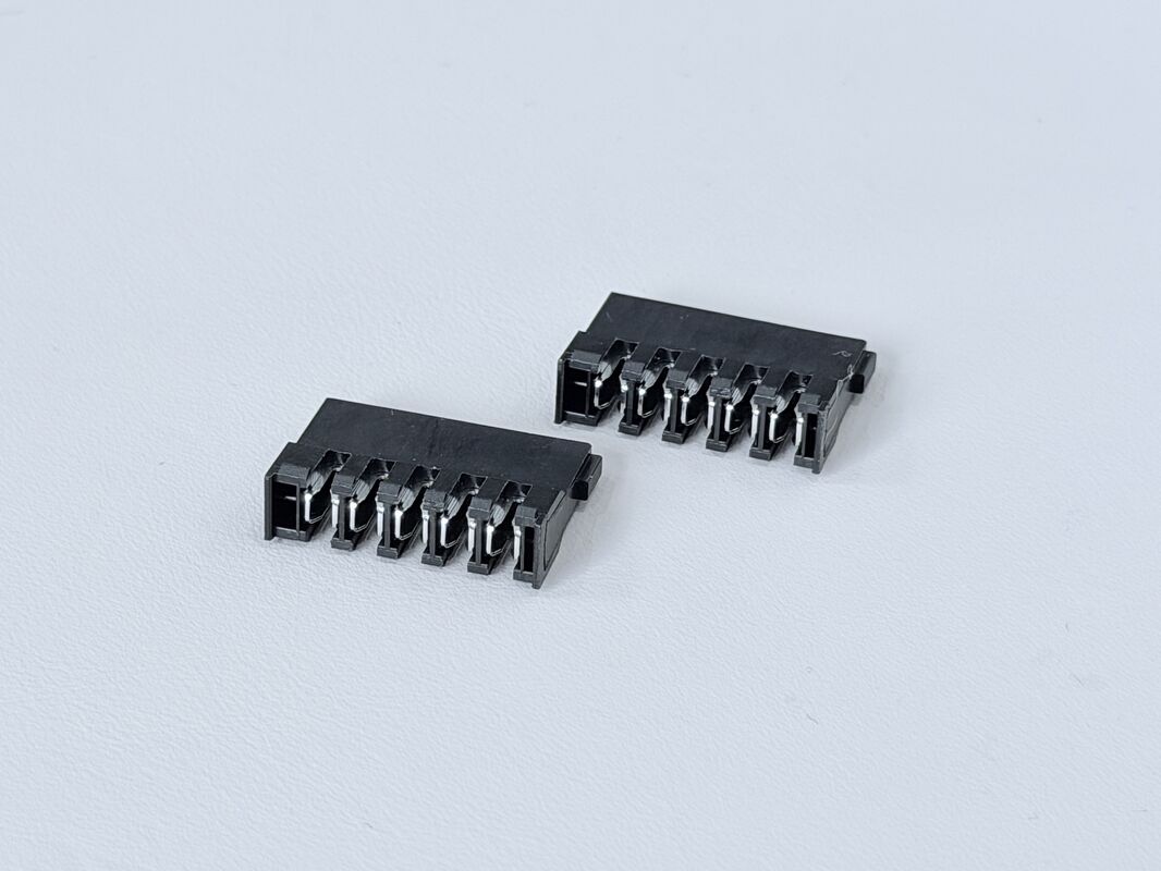
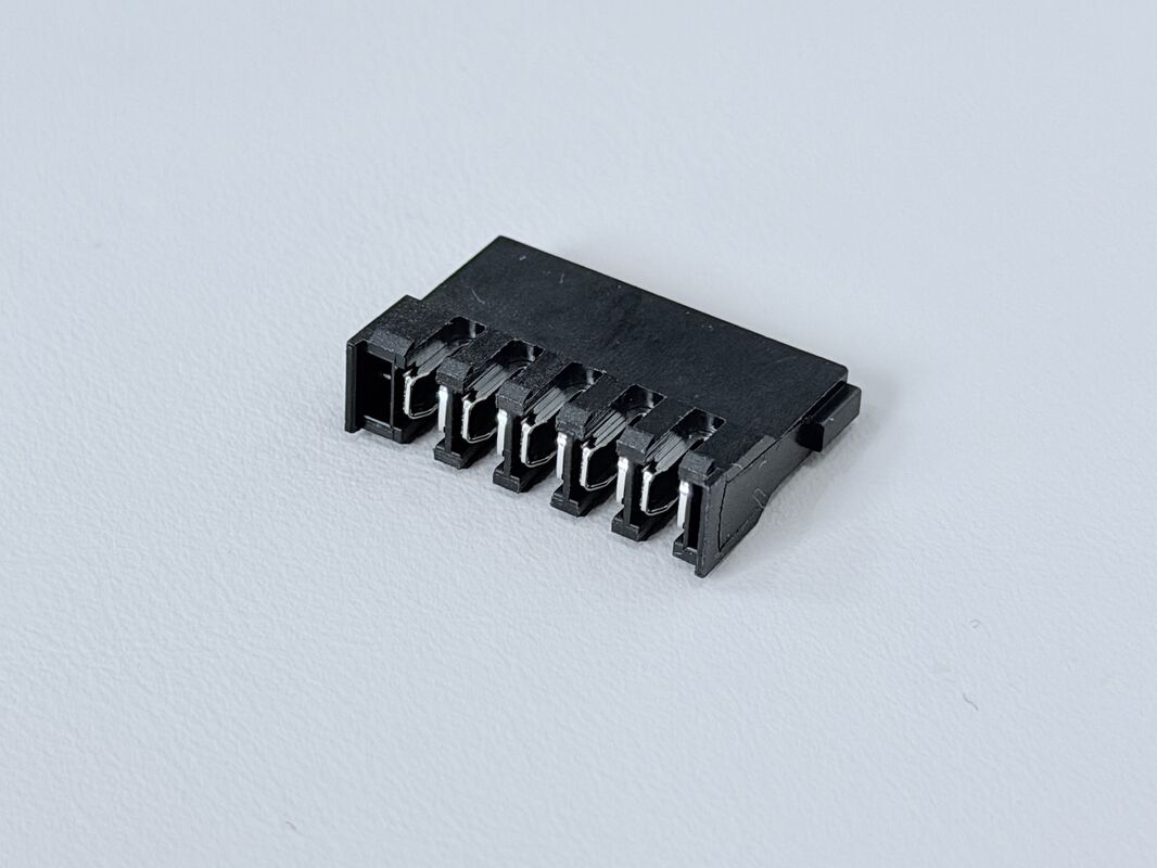
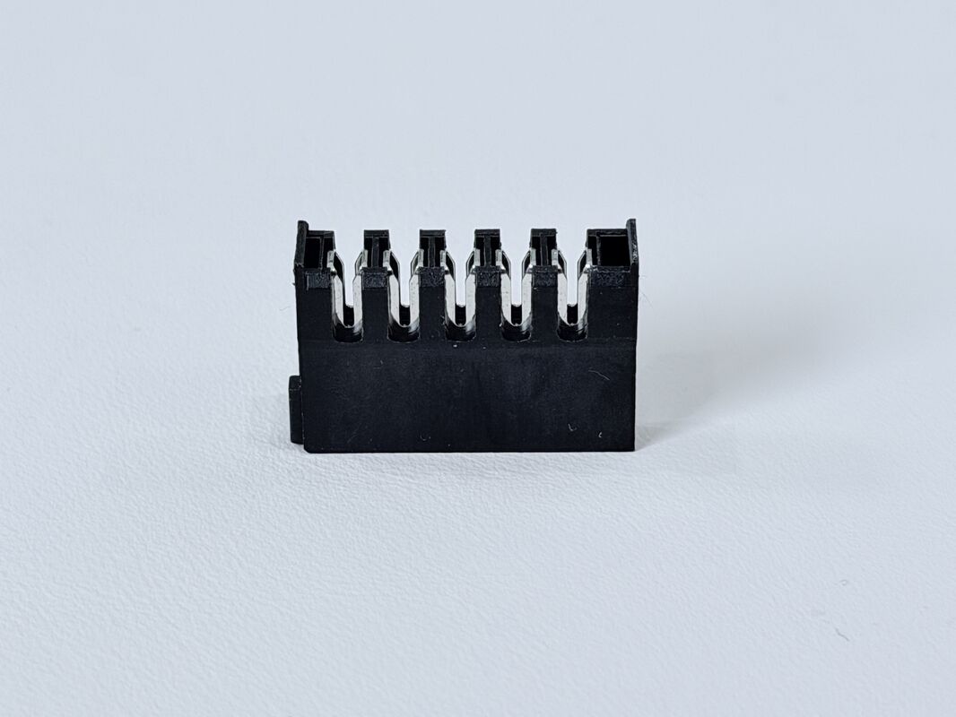
The SATA 15P Female Connector features a puncture-type terminal design for 18AWG wire, offering stable wire-to-terminal contact for power and signal applications. The terminals are plated with ≥50µ” nickel, while the contact area is finished with 15µ” gold to ensure reliable conductivity and corrosion resistance.
The connector housing is made of UL94-V0 rated PBT (20%GF), providing excellent mechanical strength and heat resistance. It supports an operating temperature range of –20°C to +85°C and maintains performance in demanding environments.
Electrical performance includes 1.5A @ 40VAC rated current, ≤30mΩ contact resistance, ≥1000MΩ insulation resistance, and 500VAC withstand voltage. Mechanical reliability is supported by ≤45N mating force, ≥15N unmating force, and ≥0.8Kgf pin retention force, ensuring secure and stable connections.
This connector is suitable for wire-to-board SATA power applications, servers, storage devices, and various electronic equipment requiring stable power and signal transmission. It is RoHS 2.0 compliant.

| Product Type |
SATA 15P Female Connector (Puncture-Type Terminal with 18# wire) |
| Operating Temperature |
–20°C to +85°C |
| Rated Current |
1.5A @ 40VAC |
| Contact Resistance |
≤ 30mΩ |
| Withstand Voltage |
500VAC / minute |
| Insulation Resistance |
≥ 1000MΩ |
| Terminal Plating |
Ni ≥ 50u” over terminal |
| Contact Area Gold Plating |
Au 15u” |
| Tin Plating (Solder/Crimp) |
Tin ≥ 80u” |
| Mating Force |
≤ 45N |
| Unmating Force |
≥ 15N for 1–5 cycles, ≥10N for 6–50 cycles |
| Single Pin Retention Force |
≥ 0.8 Kgf |
| Salt Spray Test |
24 Hours |
| Environmental Standard |
RoHS 2.0 |
| Terminal Material |
Bronze C5191-H, T=0.30 (from BOM) |
| Housing Material |
PBT 20% GF Black UL94-V0 |
| Wire Compatibility |
18# wire puncture connection |
| Structure Type |
Puncture (Pierce) terminal design |
⚙️ Applications
- Server & Data Center Equipment – Used as SAS / SATA electronic signal and power connectors on HDD/SSD backplanes, RAID cards, JBOD/NAS and 1U/2U server boards.
- Communication & Networking Systems – For routers, switches, base stations and other networking equipment that need compact PCB connectors and reliable high-speed transmission.
- Industrial & Automation Electronics – Applied in industrial PCs, PLCs, motion controllers, data loggers and test instruments as PCB-to-wire or cable connectors.
- Automotive & New Energy Applications – Used in in-vehicle data recorders, infotainment units, EV chargers and energy-storage systems for signal and low-power transmission.
- Custom Wire Harness & Cable Assemblies – Suitable for OEM/ODM projects that require connector customization for PCB, wire and cable layouts in electrical and electronic devices.
⚠️ Notes
- Make sure the working voltage, current and temperature of your design stay within the connector’s rated values, with proper safety margin.
- Design PCB pads, holes and mechanical space according to the drawing and pitch, and avoid bending or twisting stress on the connector after soldering or assembly.
- Select appropriate wire gauge, insulation and cable structure based on current load, signal speed and bending requirements for both power and signal terminals.
- For IDC / crimp types, use matched tooling and press-force to ensure full insulation displacement; for solder types, follow a controlled soldering profile to avoid overheating the LCP housing.
- Insert and pull out the connector along the mating direction, avoid pulling on the cable itself, and do not exceed the specified mating/unmating force or durability cycles.
- Keep gold-plated contact areas clean and dry, avoid touching them with bare fingers, and store products in dry anti-static packaging before assembly.

 Your message must be between 20-3,000 characters!