Our SAS 3.0/4.0 series connectors deliver exceptional data transfer speeds of up to 24 Gb/s, ensuring stable and efficient transmission for enterprise storage and server systems. Designed with high reliability and hot-plug capability, each connector undergoes strict quality control and automated precision manufacturing. With flexible customization options and strong R&D support, our SAS connectors are ideal for both board-to-board and wire-to-board applications in enterprise storage systems, servers, and data centers requiring consistent, high-speed performance. ShuangYi Precision — Powering Smarter Connections.
ShuangYi Precision — Powering Smarter Connections.
Why Choose Us:
• Free samples available for quality evaluation.
• Support for both OEM & ODM customization.
• Trade Terms: EXW, FOB, CIF, CPT, etc.
Notice: The displayed price is only for reference. Contact us now for the best offer and detailed quotation!
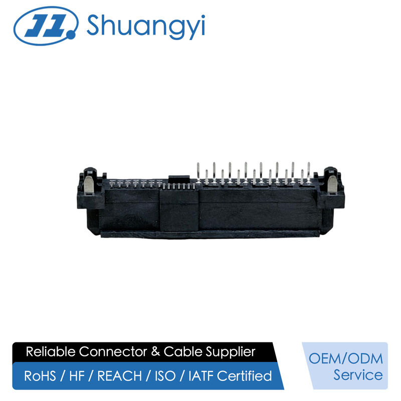
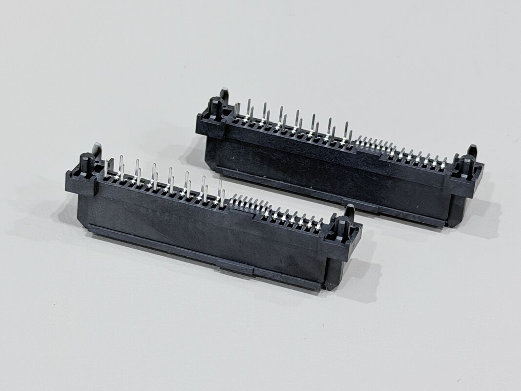
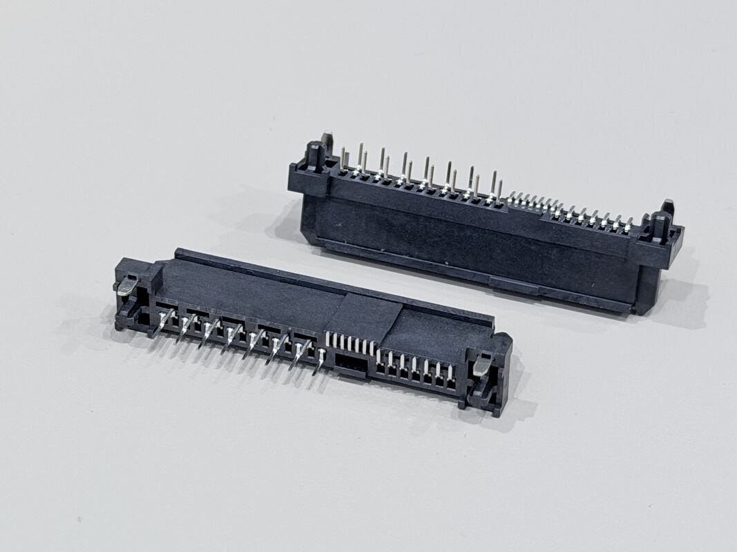
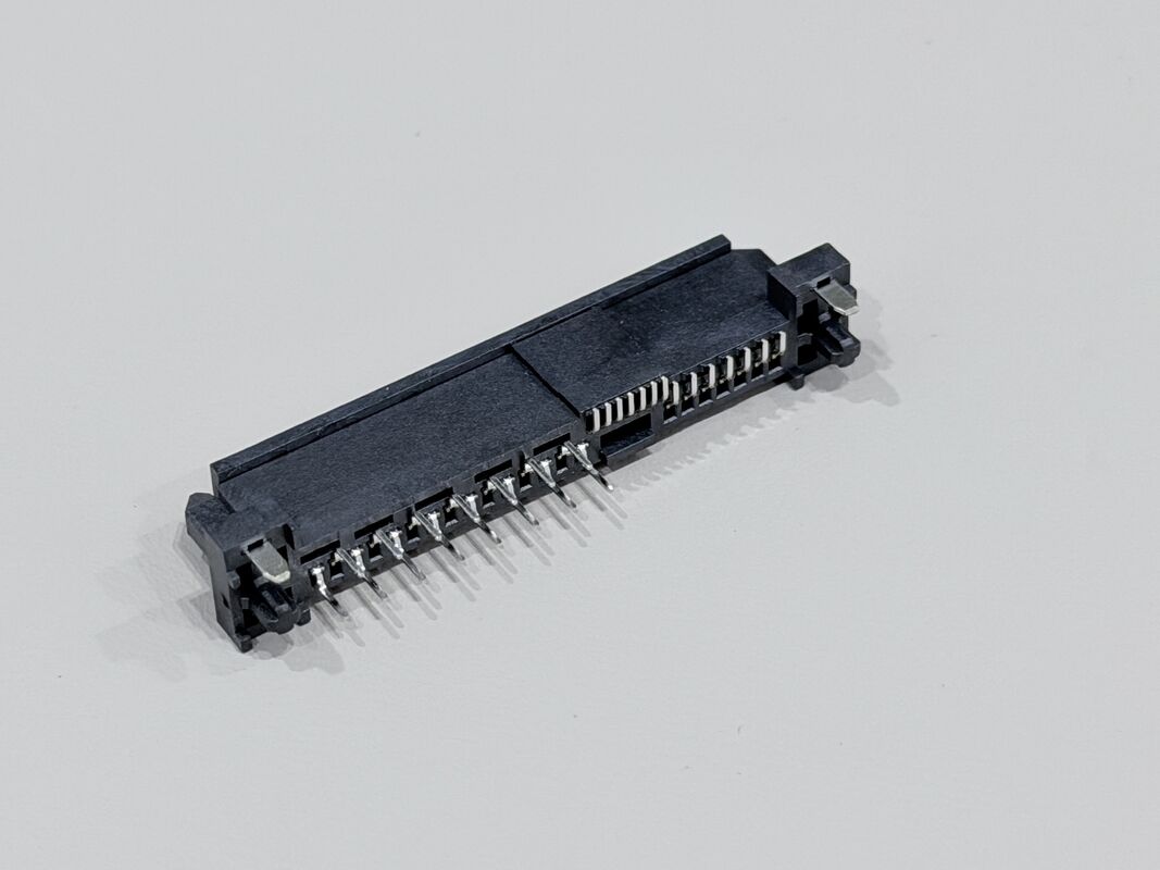
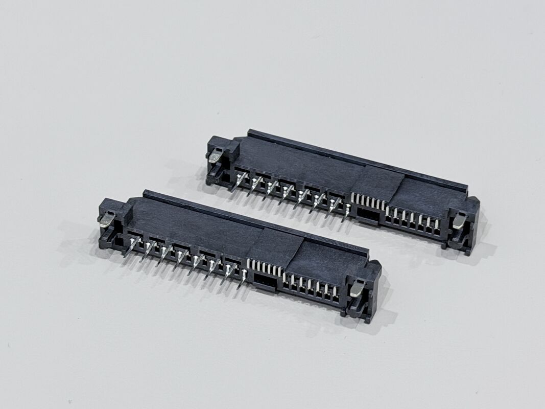
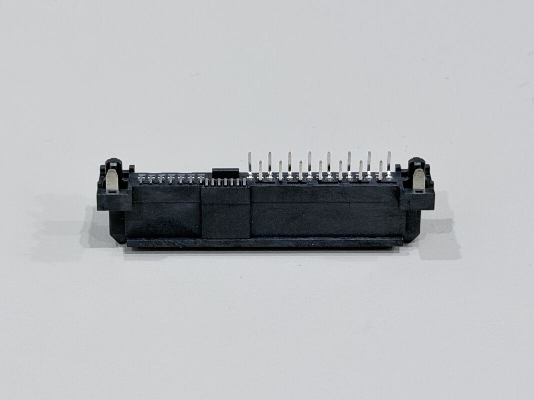
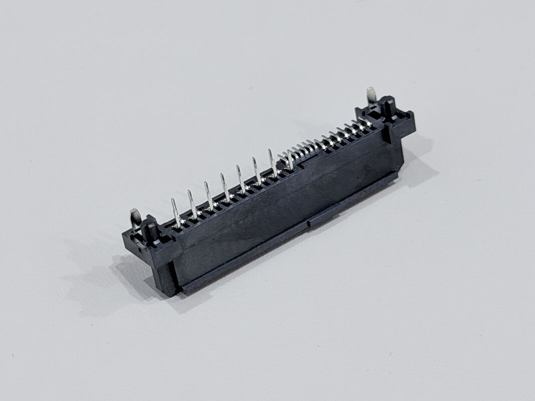
This SAS 3.0 29Pin female connector is designed for high-speed electronic signal and low-power transmission in compact server, storage and industrial systems. With a 1.27mm pitch and a mixed 7SMT + 7SMT + 15TH structure, it combines the high-density advantages of SMT pads with the mechanical strength of through-hole pins, providing a reliable PCB connector solution for both signal and power lines.
Terminals are stamped from phosphor bronze C5191-H and finished with a multilayer plating system: 50µ" nickel underplate for corrosion resistance, 30µ" gold on the contact area to ensure stable low-resistance signal paths, and 80µ" tin on the solder area for strong solder joints to the PCB. The peg is made from brass C2680-H with Ni/Sn plating to improve positioning and mechanical retention. The housing and cap use glass-filled LCP, black, UL94-V0, providing excellent heat resistance, dimensional stability and flame retardancy.
Electrically, the connector is rated at 1.5A @ 40VAC, with contact resistance ≤30mΩ, insulation resistance ≥1000MΩ, and 500VAC dielectric withstand. Mechanically, it supports up to 500 mating cycles on the backplane side and 25 cycles on the cable side under EIA 364-09, with controlled mating and unmating forces to protect the PCB and solder joints. This makes it an ideal connector choice for customized PCB, wire and cable layouts in servers, communication equipment, automotive electronics and other high-reliability applications.

| Product Type |
SAS 3.0 29Pin straight female connector, mixed 7SMT + 7SMT + 15TH pin configuration |
| Interface Series |
SAS 3.0 series |
| Number of Positions |
29 pins (7 + 7 high-speed signal pins, 15 power/ground pins) |
| Pitch |
1.27mm (typical SAS pitch) |
| Gender |
Female connector |
| Mounting Style |
Mixed mounting: 14 pins SMT to PCB + 15 pins Through-Hole (TH) to PCB |
| Rated Current / Voltage |
1.5A @ 40VAC |
| Operating Temperature |
–20°C to +85°C |
| Contact Resistance |
≤ 30mΩ (Max) |
| Insulation Resistance |
≥ 1000MΩ (Min) |
| Withstand Voltage |
500VAC / minute |
| Mating Force |
Backplane ≤ 25N max; cable ≤ 50N max |
| Unmating Force |
Backplane ≥ 5N min; cable ≥ 20N min |
| Mating Durability |
Up to 200 cycles/hour; backplane 500 cycles, cable 25 cycles (per EIA 364-09) |
| Contact Base Material |
Phosphor Bronze C5191-H, t = 0.25mm |
| Contact Plating – Underlayer |
Ni 50µ" min plated over terminal |
| Contact Plating – Contact Area |
Au 30µ" min plated on contact area |
| Plating – Solder Area |
Sn 80µ" min plated on solder area |
| Peg Material |
Brass C2680-H, t = 0.30mm, Ni 50µ" min + Sn 40µ" min plated |
| Housing Material |
LCP E130I G/F, black, UL94-V0 |
| Cap Material |
LCP G/F, black, UL94-V0 |
| Salt Spray Test |
Gold-plated |
Key Features
- True SAS 29P female connector with 1.27mm pitch for high-density PCB layouts
- Right-angle (R90°) solder wire design optimizes cable routing in slim server and industrial enclosures
- Ni 50U" + Au 15U" + Sn 80U" plating for excellent conductivity, low contact resistance and long-term corrosion resistance
- Phosphor bronze C5191-H terminals provide stable contact force and durability under vibration and thermal cycling
- LCP G/F UL94-V0 HF housing ensures high mechanical strength and heat resistance for demanding electronic environments
- Positioning peg and thick back cover enhance assembly accuracy, cable strain relief and mechanical stability
- Defined mating / unmating forces and single-pin retention ≥0.8kgf guarantee secure, reliable connections in wiring harnesses
- Suitable for electrical power and electronic signal transmission, compatible with customization for different wire gauges and cable types
⚙️ Applications
- Server & Data Center Equipment – Used as SAS / SATA electronic signal and power connectors on HDD/SSD backplanes, RAID cards, JBOD/NAS and 1U/2U server boards.
- Communication & Networking Systems – For routers, switches, base stations and other networking equipment that need compact PCB connectors and reliable high-speed transmission.
- Industrial & Automation Electronics – Applied in industrial PCs, PLCs, motion controllers, data loggers and test instruments as PCB-to-wire or cable connectors.
- Automotive & New Energy Applications – Used in in-vehicle data recorders, infotainment units, EV chargers and energy-storage systems for signal and low-power transmission.
- Custom Wire Harness & Cable Assemblies – Suitable for OEM/ODM projects that require connector customization for PCB, wire and cable layouts in electrical and electronic devices.
⚠️ Notes
- Make sure the working voltage, current and temperature of your design stay within the connector’s rated values, with proper safety margin.
- Design PCB pads, holes and mechanical space according to the drawing and pitch, and avoid bending or twisting stress on the connector after soldering or assembly.
- Select appropriate wire gauge, insulation and cable structure based on current load, signal speed and bending requirements for both power and signal terminals.
- For IDC / crimp types, use matched tooling and press-force to ensure full insulation displacement; for solder types, follow a controlled soldering profile to avoid overheating the LCP housing.
- Insert and pull out the connector along the mating direction, avoid pulling on the cable itself, and do not exceed the specified mating/unmating force or durability cycles.
- Keep gold-plated contact areas clean and dry, avoid touching them with bare fingers, and store products in dry anti-static packaging before assembly.

 Your message must be between 20-3,000 characters!