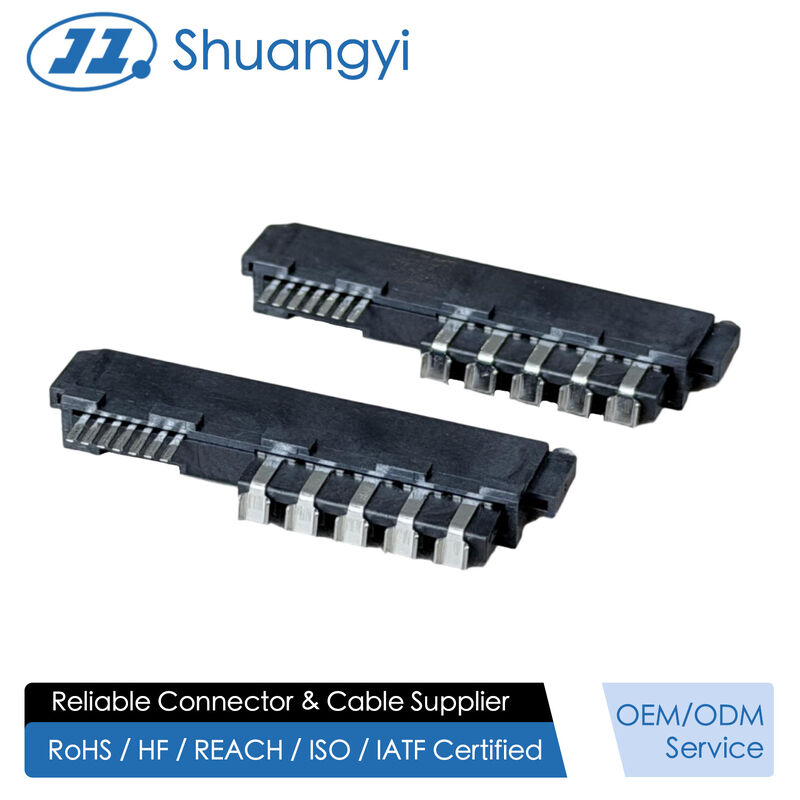
Our SAS 3.0/4.0 series connectors deliver exceptional data transfer speeds of up to 24 Gb/s, ensuring stable and efficient transmission for enterprise storage and server systems. Designed with high reliability and hot-plug capability, each connector undergoes strict quality control and automated precision manufacturing. With flexible customization options and strong R&D support, our SAS connectors are ideal for both board-to-board and wire-to-board applications in enterprise storage systems, servers, and data centers requiring consistent, high-speed performance. ShuangYi Precision — Powering Smarter Connections.
ShuangYi Precision — Powering Smarter Connections.
Why Choose Us:
• Free samples available for quality evaluation.
• Support for both OEM & ODM customization.
• Trade Terms: EXW, FOB, CIF, CPT, etc.
Notice: The displayed price is only for reference. Contact us now for the best offer and detailed quotation!
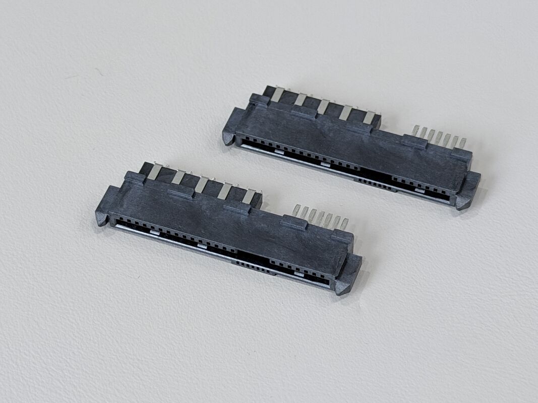
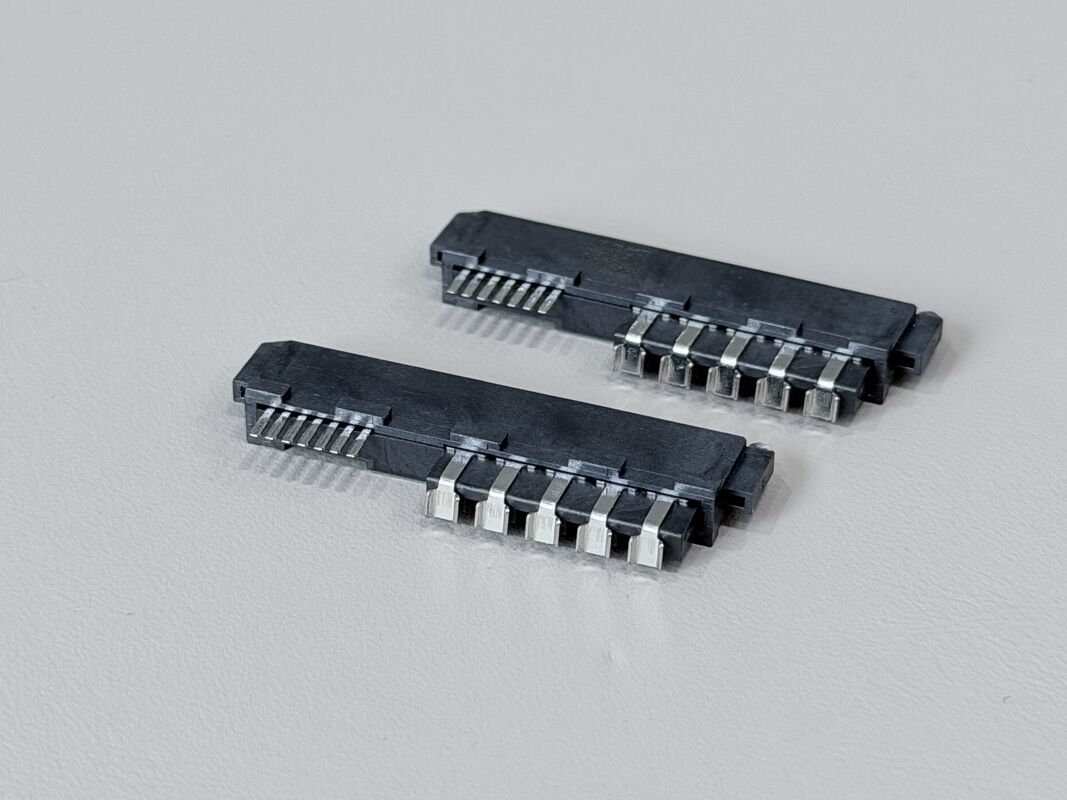
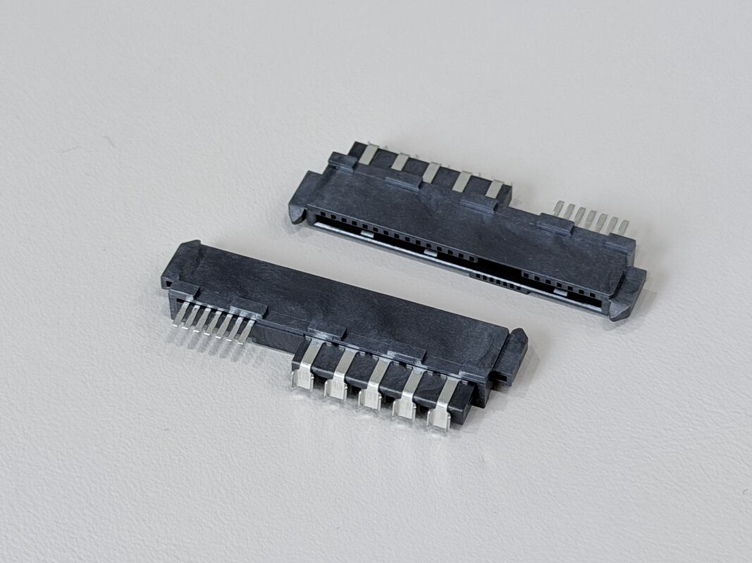
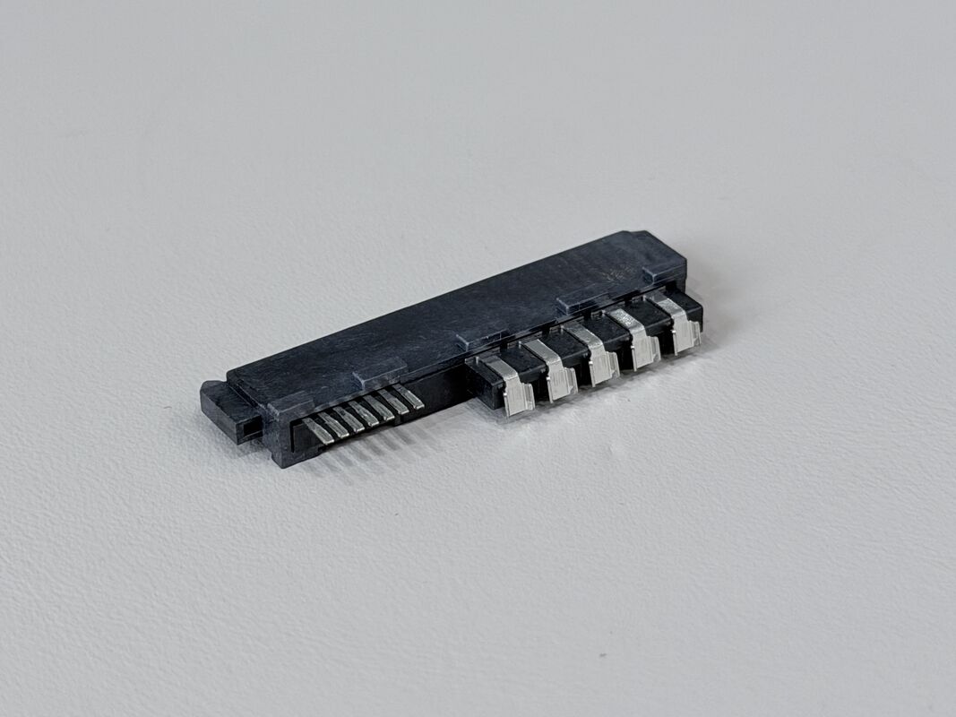
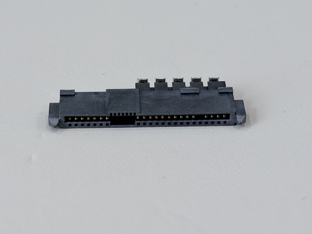
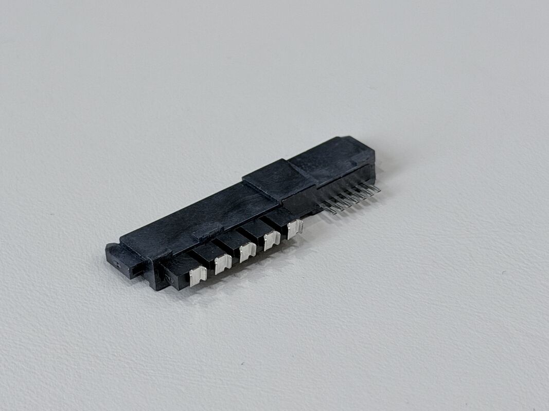
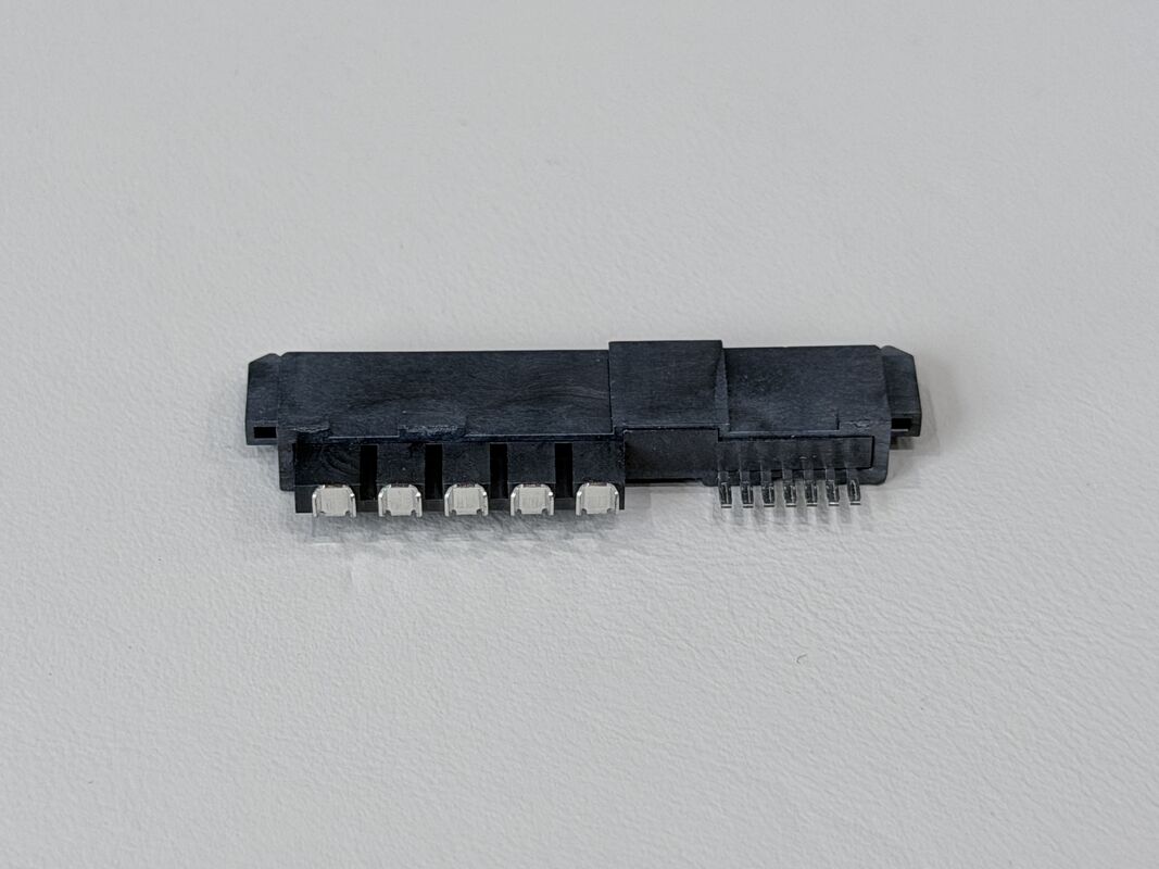
The SAS 29P Mixed Angle Female Connector with Positioning Peg is a specialized electronic signal and power connector designed for SAS-based server, storage and industrial systems. It features a dummy 29-pin layout where the 11th pin is intentionally left vacant, and a mixed-angle structure with 15 pins bent down 90° and 7 pins straight 180°, allowing highly flexible routing for PCB and wire-cable assemblies.
Terminals are produced from phosphor bronze C5191-H (t = 0.25mm) and finished with a robust three-layer plating system:
-
Nickel ≥50u" under the gold area and nickel ≥25u" under the tin area for corrosion resistance;
-
15u" minimum gold on the contact area to ensure low contact resistance and stable high-speed electrical signal performance;
-
80u" minimum tin on the solder & crimp area for strong, reliable solder joints to copper wires.
The connector uses glass-filled LCP housing and base (black, UL94-V0, Halogen-Free), delivering excellent mechanical strength, dimensional stability and heat resistance for demanding electrical and electronic environments.
Electrical performance includes a rated current of 1.5A @ 40VAC, contact resistance ≤30mΩ, insulation resistance ≥1000MΩ, and withstand voltage 500VAC/minute. Mechanically, the connector supports mating force up to 50N, unmating force at least 20N, single pin retention ≥0.8kgf, and 25 mating cycles at 200 cycles/hour, ensuring long-term stability.
A positioning peg and housing bump (top boss) provide accurate alignment and additional mechanical locking, making this connector ideal for customized PCB, wire and cable configurations in space-constrained systems.

| Interface Series |
SAS series |
| Number of Positions |
29 pins (dummy layout, 1 pin empty) |
| Pitch of Housing |
1.27mm (C: 1.27 pitch of housing) |
| Gender |
Female connector |
| Structure |
Mixed angle: 15 pins bent down 90°, 7 pins straight 180°, 11th pin no contact; with locating peg and housing bump |
| Termination Style |
Way of terminal with wire: SS3 (solder / wire-termination style, per code) |
| Rated Current / Voltage |
1.5A @ 40VAC |
| Operating Temperature |
–20°C to +85°C |
| Contact Resistance |
≤ 30mΩ (Max) |
| Withstand Voltage |
500VAC / minute |
| Insulation Resistance |
≥ 1000MΩ (Min) |
| Terminal Plating – Base A |
Ni ≥ 50u" min plated over terminal under gold area |
| Terminal Plating – Base B |
Ni ≥ 25u" min plated over terminal under tin area |
| Contact Area Plating |
Au 15u" min plated on contact area |
| Solder & Crimp Area Plating |
Sn 80u" min plated on solder & crimp area |
| Mating Force |
≤ 50N max |
| Unmating Force |
≥ 20N min |
| Mating / Unmating Durability |
200 cycles/hour max, 25 cycles (per EIA 364-09) |
| Single Pin Retention Force |
≥ 0.8kgf per pin |
| Salt Spray Test |
Gold area ≥ 48 hours |
| Housing Material |
LCP G/F, Black, UL94-V0, Halogen-Free (HF) – HSS-C29F-002 / BSS-C29F-039 |
| Terminal Material |
Phosphor Bronze C5191-H, t = 0.25mm (TS-C07F-S04, TS-C15F-S96) |
| Environmental |
Halogen-Free (HF) materials |
| Special Features |
Positioning peg for accurate location, top boss for mechanical guidance, mixed-angle pin layout for flexible PCB & cable routing |
Key Features
- Dummy SAS 29P female connector with one empty pin (11th pin), optimized for special coding or isolation requirements
- Mixed-angle terminals: 15 pins down-bent 90° and 7 pins straight 180°, enabling flexible PCB trace and wire-cable routing
- 1.27mm pitch high-density design, suitable for compact PCB connector layouts
- Ni + Au + Sn multi-layer plating (Ni 50u"/25u", Au 15u", Sn 80u") for reliable electrical performance and long-term corrosion resistance
- Phosphor bronze C5191-H terminals provide strong spring force and durability under vibration and repeated mating
- LCP G/F UL94-V0 HF housing ensures high mechanical strength and heat resistance in harsh electronic environments
- Positioning peg and top boss improve assembly accuracy and mechanical retention in PCB and cable assemblies
- Defined mating/unmating forces and single-pin retention ≥0.8kgf guarantee secure connections during handling and operation
- Suitable for electrical / electronic signal and power transmission, especially in server, storage and automotive applications where customization is required
⚙️ Applications
- This SAS 29P female connector is suitable for a variety of electrical / electronic uses:
- Server & Data Center Equipment
- Dummy or special-coding connectors on SAS backplanes
- PCB connectors for controller boards, test boards and interposers in data-center servers
- Storage & Communication Systems
- HDD/SSD interface boards where specific pins must be isolated or used for mechanical keying
- Communication equipment using SAS-style high-speed signal connectors
- Automotive & Industrial Electronics
- Data logging units, industrial PCs and testers that need customized SAS-type connector footprints
- Wiring harness modules where mixed-angle pins simplify cable routing and stress relief
- Custom PCB & Wire Cable Assemblies
- OEM / ODM projects requiring connector-level customization (dummy pins, special angles, position coding)
- Electrical signal and power connectors in compact devices where standard SAS connectors cannot meet layout constraints
⚠️ Notes
-
Design the PCB pad and hole layout according to the 1.27mm pitch and mixed-angle structure (15P 90° + 7P 180°) to avoid mechanical interference.
-
When soldering wires to the tin-plated areas, follow an appropriate soldering profile to ensure full wetting and reliable joints while protecting the LCP housing.
-
Keep gold-plated contact areas clean; avoid touching the terminals with bare hands to prevent contamination and oxidation.
-
Make full use of the positioning peg and housing bump for accurate alignment in fixtures, housings or over-molded shells, reducing stress on terminals.
-
Do not exceed the specified mating/unmating forces and mating cycles to maintain terminal elasticity and connector life.
-
Store connectors in dry, anti-static packaging, and handle them in ESD-protected areas when assembling into sensitive electronic equipment.
-
Operate the connector only within the rated temperature range (–20°C to +85°C) and electrical ratings to ensure long-term reliability.

 Your message must be between 20-3,000 characters!