Our SATA connector series is designed for stable data transmission and high reliability. With customizable pin count, pitch, materials, and plating specifications, we offer tailored solutions for diverse applications. Produced in our automated facilities with strict quality control, these connectors ensure excellent durability, heat resistance, and hot-swap performance. Widely used in computers, servers, and industrial storage devices, they deliver precision connection and long-lasting performance.
ShuangYi Precision — Powering Smarter Connections.
Why Choose Us:
• Free samples available for quality evaluation.
• Support for both OEM & ODM customization.
• Trade Terms: EXW, FOB, CIF, CPT, etc.
Notice: The displayed price is only for reference. Contact us now for the best offer and detailed quotation!
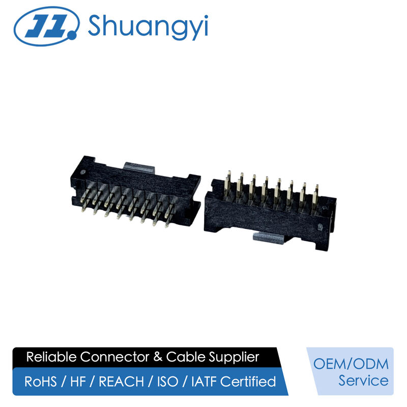
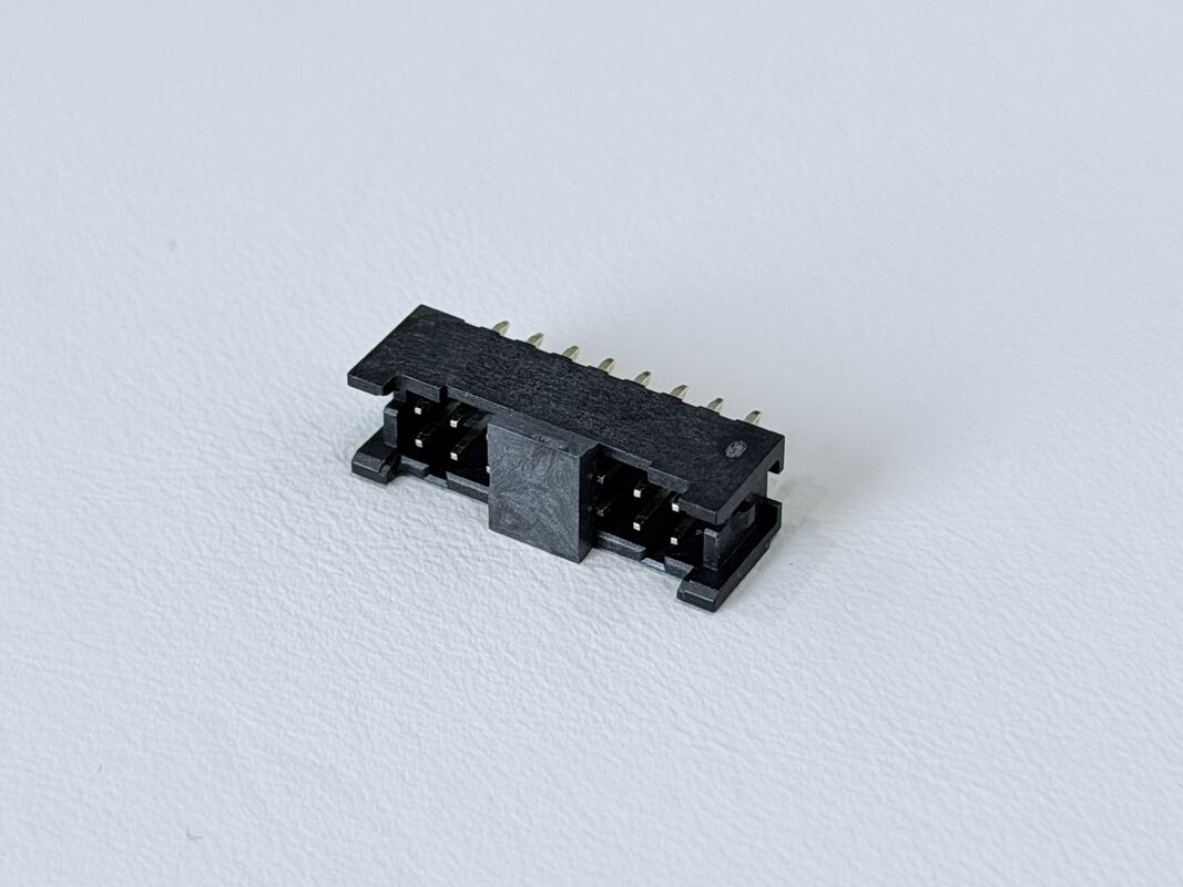
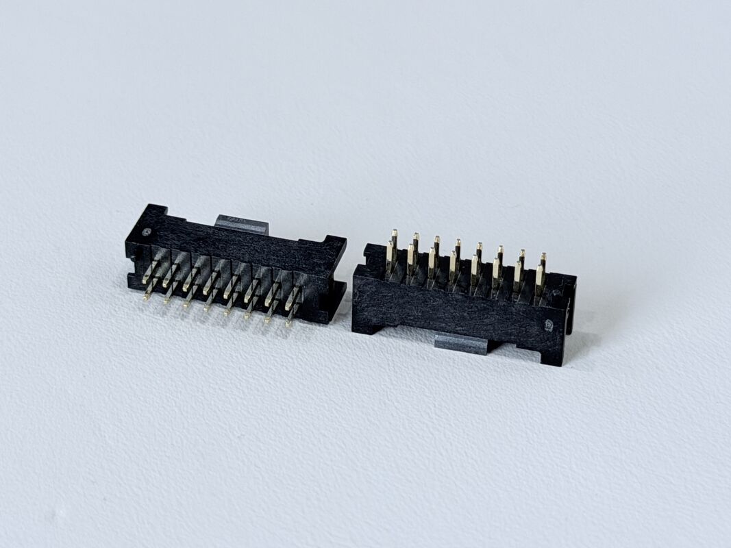
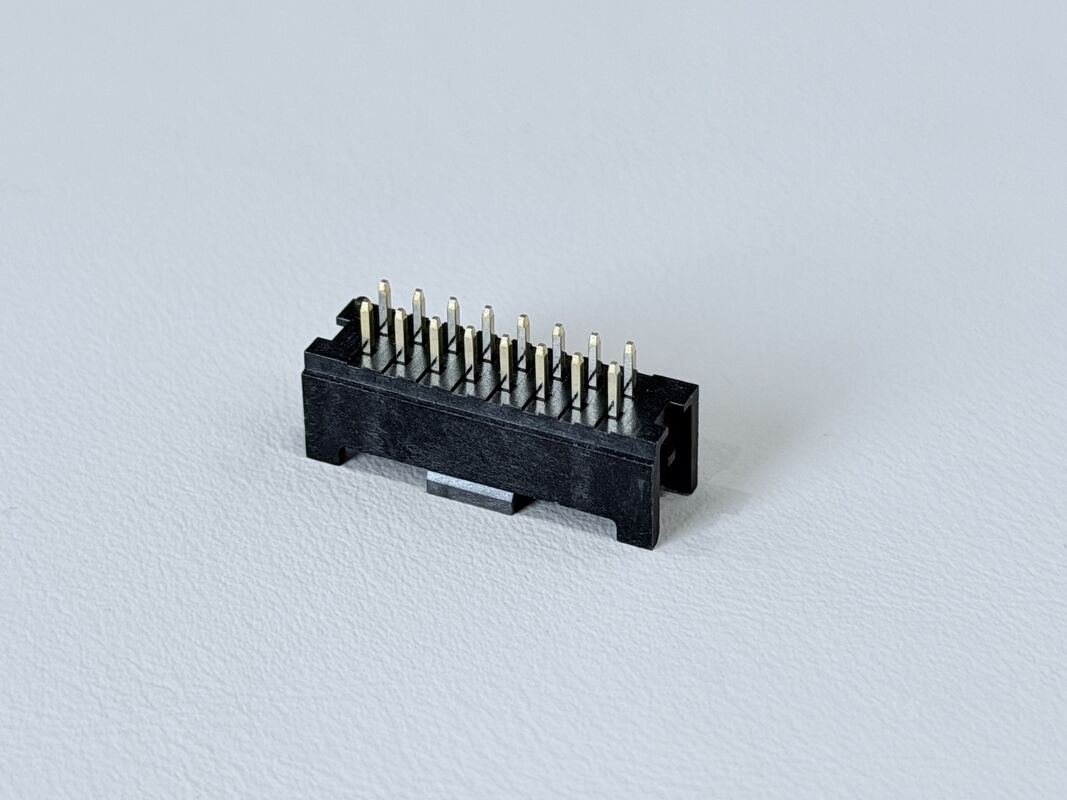
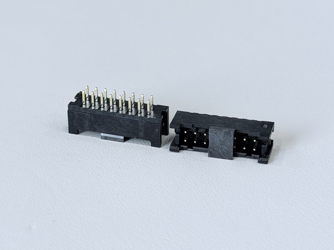
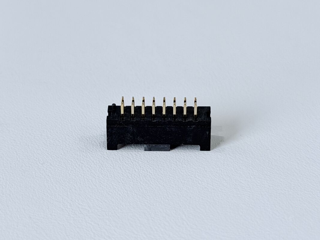
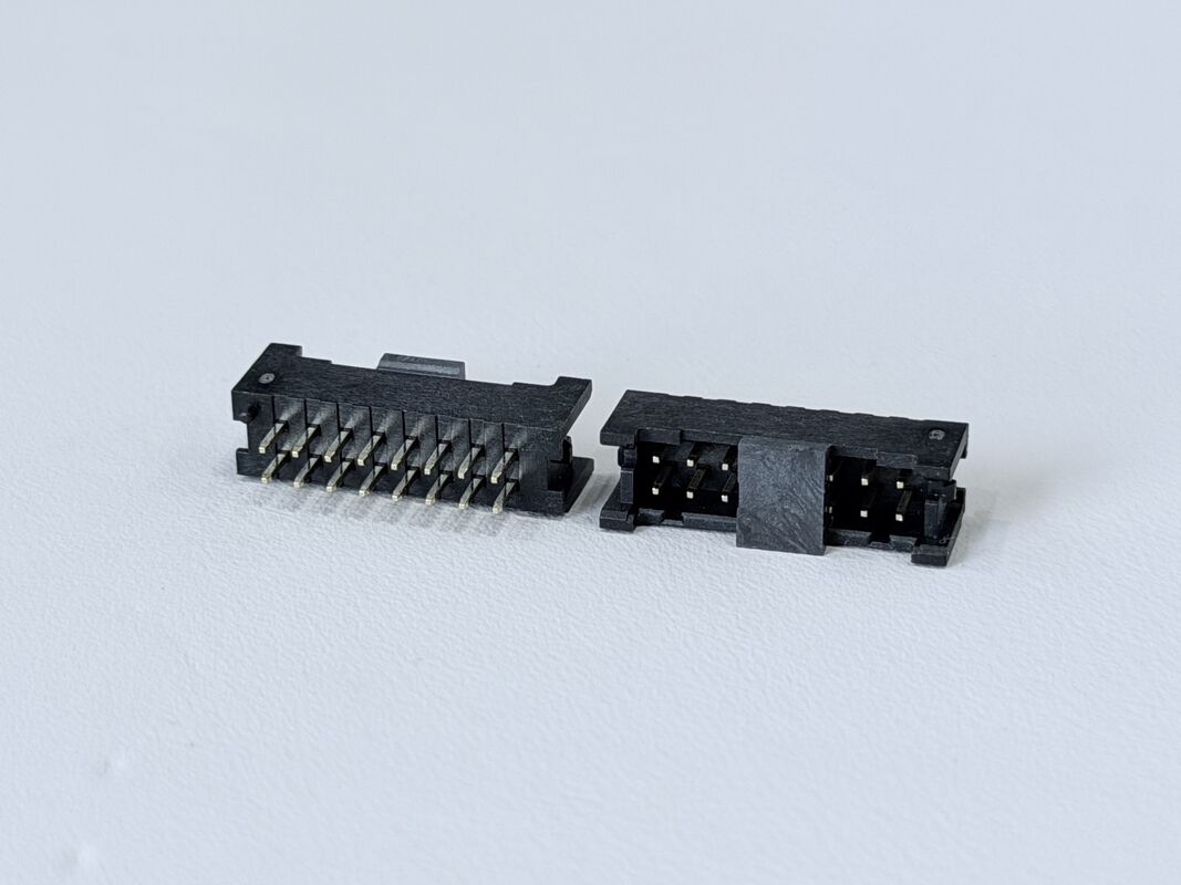
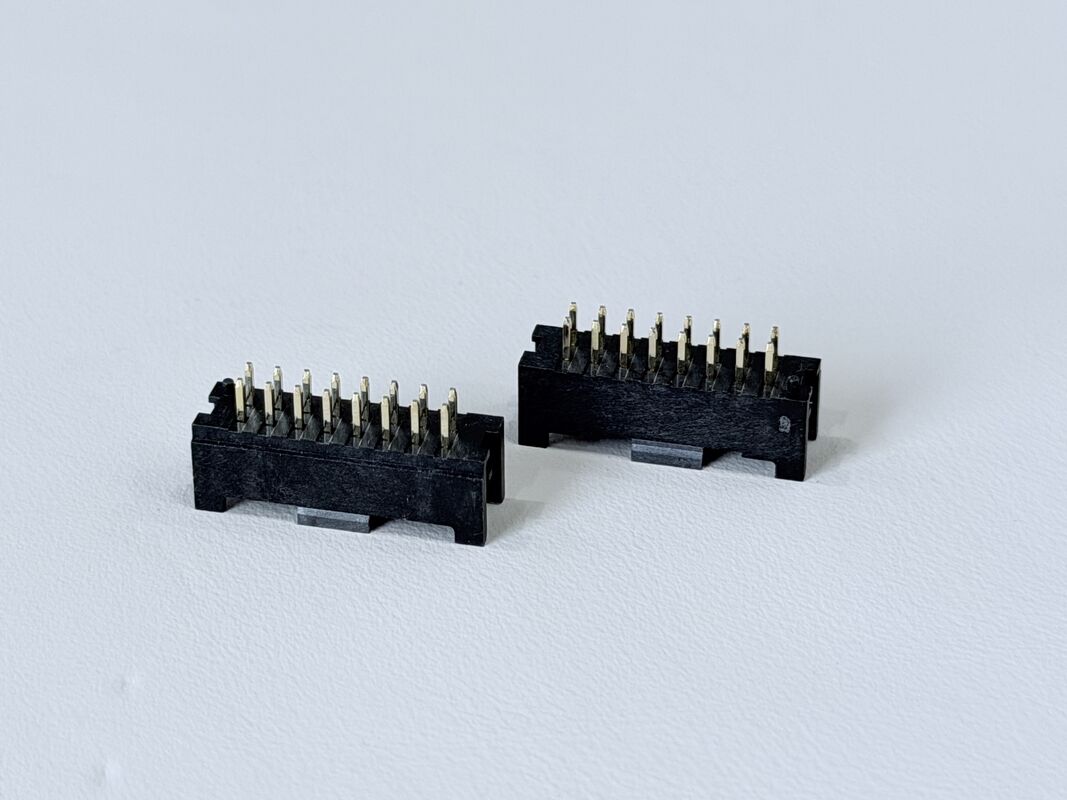
This 2×8 Pin Header Connector with a 2.00mm pitch is designed for reliable PCB-to-PCB and wire-to-board electronic signal transmission. The connector features a vertical through-hole structure with a positioning post, ensuring precise alignment during PCB assembly. Each terminal is made from high-strength copper alloy H65, while the housing uses PA9T/LCP UL94-V0 flame-retardant material, providing excellent thermal stability and mechanical durability.
The terminals are plated with a minimum 30u” nickel base and gold/tin G/F finish, offering improved corrosion resistance and long-term conductivity. With a rated current of 1.5A per pin, initial contact resistance ≤10mΩ, and insulation resistance ≥1000MΩ, the connector ensures stable electrical performance even under demanding environments.
This pin header is ideal for applications requiring compact structure, strong retention, and consistent signal integrity, and supports use in custom wiring, PCB modules, industrial systems, servers, automotive electronics, and power-signal transmission.

| Product Type |
Pin Header Connector |
| Configuration |
2×8 Pins, Dual-Row |
| Pitch |
2.00 mm |
| Mounting Style |
Vertical PCB Through-Hole |
| Post Design |
With Positioning Post (with stand-off column) |
| Tail Length |
3.0 mm (rear tail) |
| Rated Current |
1.5A per pin (Max.) |
| Plating |
Ni 30u” Min, Gold/Tin G/F, Salt-spray 24H |
| Insulation Material |
PA9T / LCP Black UL94-V0 |
| Terminal Material |
Copper Alloy H65 |
| Operating Temperature |
–25°C to +85°C |
| Contact Resistance |
Initial ≤10mΩ; After environment ≤20mΩ |
| Insulation Resistance |
≥1000MΩ |
| Withstanding Voltage |
800V AC/minute |
| Environmental |
ROHS 2.0 / HF |
| Application Type |
PCB Wire-to-Board Electronic Signal Transmission |
⚙️ Applications
- PCB Signal & Data Transmission: Used for board-to-board or board-to-module connections, including low-voltage signals, data transmission, and control interfaces.
- Consumer Electronics: Common in smart home appliances, printers, cameras, displays, controllers, and handheld devices for internal signal routing.
- Industrial Automation & Control Systems: Applied in PLCs, industrial control boards, sensors, meters, robotics modules, and automation I/O interfaces.
- Servers & Data Center Equipment: Used for backplane interfaces, storage modules, communication boards, and signal expansion connectors.
- Automotive Electronics: Suitable for ECUs, BMS modules, sensor units, dashboards, infotainment systems, and on-board control interfaces.
- Communication & Networking Devices: Used in routers, switches, IoT gateways, RF modules, and network communication cards.
- IoT & Smart Device Modules: Applied in Bluetooth modules, WiFi modules, GPS/Beidou modules, sensor nodes, and embedded system expansion ports.
- Power Control & Monitoring Boards: For auxiliary power transmission, monitoring signals, and low-power control circuits.
- Custom OEM/ODM Electronic Designs: Ideal for designs requiring customizable pin count, pitch, height, plating option, and configuration.
⚠️ Notes
- Ensure Correct Pin Alignment: Check orientation and positioning before mating to avoid mis-insertion, bent pins, or PCB pad damage.
- Do Not Exceed Electrical Ratings: Follow the specified current and voltage limits to prevent overheating or contact failure.
- Proper Insertion and Extraction Force: Avoid excessive force during mating/unmating to prevent deformation, cracked solder joints, or pin damage.
- Keep Contact Surfaces Clean: Ensure terminals remain free from dust, oil, oxidation, or contaminants that reduce conductivity.
- Follow Recommended Soldering Conditions: Use appropriate soldering temperature profiles according to plastic materials such as LCP, PA6T, PA66, or PBT.
- Verify PCB Hole Tolerance: Incorrect hole size may cause inadequate solder filling or mechanical instability.
- Avoid Mechanical Stress After Assembly: Do not apply lateral pressure or bending forces, especially for SMT pin headers.
- Maintain Proper Storage Conditions: Store in a dry, dust-free environment to prevent terminal oxidation; use anti-static packaging if required.
- Confirm Compatibility with Female Header: Ensure matching pitch, pin count, height, and contact design to avoid mating failure.
- Choose Correct Plating Specification: Select proper plating (gold, tin, nickel) based on your application’s durability, corrosion resistance, and signal reliability needs.

 Your message must be between 20-3,000 characters!